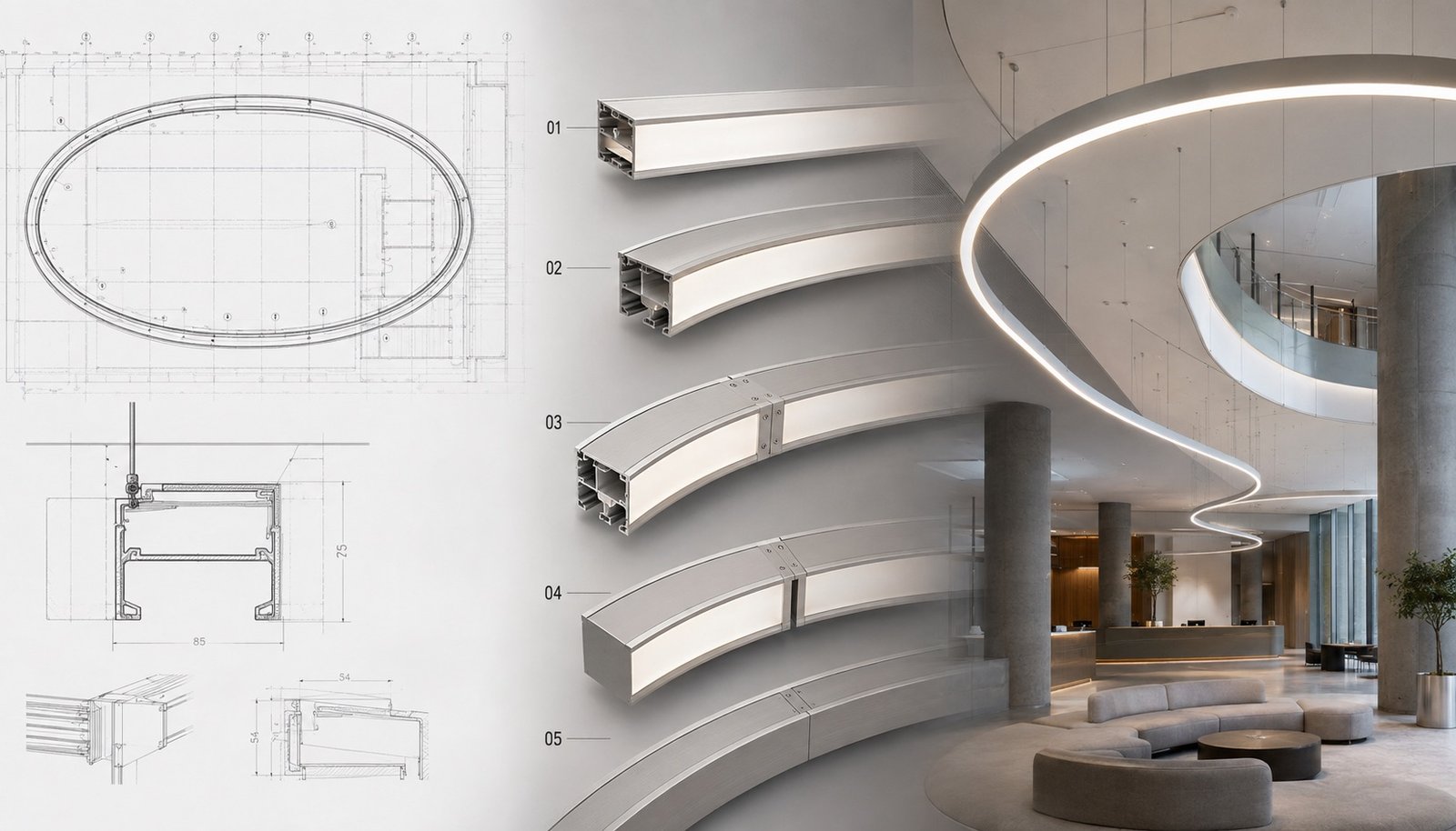
Large commercial lighting projects often begin with a simple line on a reflected ceiling plan. By the time that line becomes an installed luminaire, it may have passed through architectural coordination,
lighting calculations, profile selection, bending, machining, electrical engineering, control design, sampling, shop drawings, production, testing, packing and site assembly.
That is why custom linear lighting should not be purchased in the same way as a standard catalog fixture.
A 2-meter suspended luminaire can often be selected by model number. A 30-meter recessed run, a 6-meter-diameter circle or a multi-zone patterncrossing several ceiling types requires project engineering. The supplier needs to convert design intent into manufacturable sections that can be shipped, identified, installed and commissioned without losing the geometry shown on the drawings.
This guide explains the workflow for large custom linear lighting projects and the information that architects, lighting designers, contractors, distributors and procurement teams should control at each
stage.
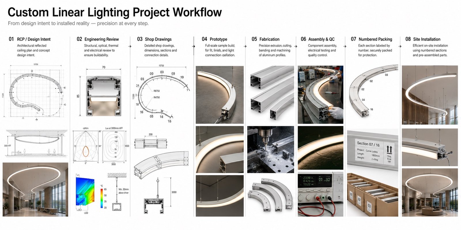
Figure 1. A custom linear lighting project workflow from design intent and engineering review through fabrication, quality control, numbered packing and site installation.
◆ What Counts as a Custom Linear Lighting Project?
Customization can involve much more than changing fixture length. Typical project-specific requirements include:
- non-standard lengths;
- special profile widths or heights;
- custom recessed apertures;
- trimless ceiling interfaces;
- custom suspension heights;
- mitered corners;
- circles and ovals;
- inward or outward curves;
- runway and capsule shapes;
- waves and free-form paths;
- direct/indirect configurations;
- special lenses or diffusers;
- project-specific wattage;
- CCT, CRI or tunable-white requirements;
- RGB/RGBW systems;
- DALI, 0-10 V, DMX or other controls;
- custom finishes;
- special feed locations;
- project-specific certification or testing;
- special packing and section identification.
The more of these variables a project combines, the more important the engineering process becomes.
◆ Why Large Commercial Projects Need a Different Workflow
Large projects introduce three forms of complexity.
▸ Geometry complexity
The luminaire may need to follow the architecture exactly. Small dimensional errors that are invisible on one fixture can become obvious over a long run or a large circle.
▸ System complexity
The project may combine LED modules, drivers, controls, emergency components, sensors and multiple electrical zones. These elements must be compatible.
▸ Logistics complexity
A large lighting feature cannot normally ship as one piece. It must be divided into sections that fit manufacturing equipment, cartons or crates, elevators, doors and site handling constraints.
The design is therefore not complete until the installation and logistics strategy are also understood.
◆ Stage 1: Start With the Right Project Information
The fastest way to delay a custom lighting project is to begin manufacturing from incomplete drawings. For initial review, provide as much of the following as possible:
- reflected ceiling plan (RCP);
- architectural floor plan;
- luminaire schedule;
- fixture tags;
- CAD/DWG or dimensioned PDF;
- ceiling sections;
- mounting details;
- quantities;
- project location;
- supply voltage;
- lighting-control specification;
- target wattage or lumen output;
- CCT and CRI;
- finish;
- certification requirements;
- required delivery date.
Not every item is necessary for a budget quotation, but critical missing information should be resolved before final shop-drawing approval.
◆ Stage 2: Read the Drawing as a Manufacturing Document
Architectural drawings communicate design intent. Manufacturing drawings must communicate exact geometry. A lighting manufacturer should identify:
- each continuous run;
- start and end points;
- straight lengths;
- corners and angles;
- radii;
- arc lengths;
- intersections;
- elevation changes;
- mounting conditions;
- power-feed locations;
- section boundaries.
For custom shapes, the most important question is: can the geometry be reproduced without interpretation?
If the answer is no, the drawing needs clarification before production.
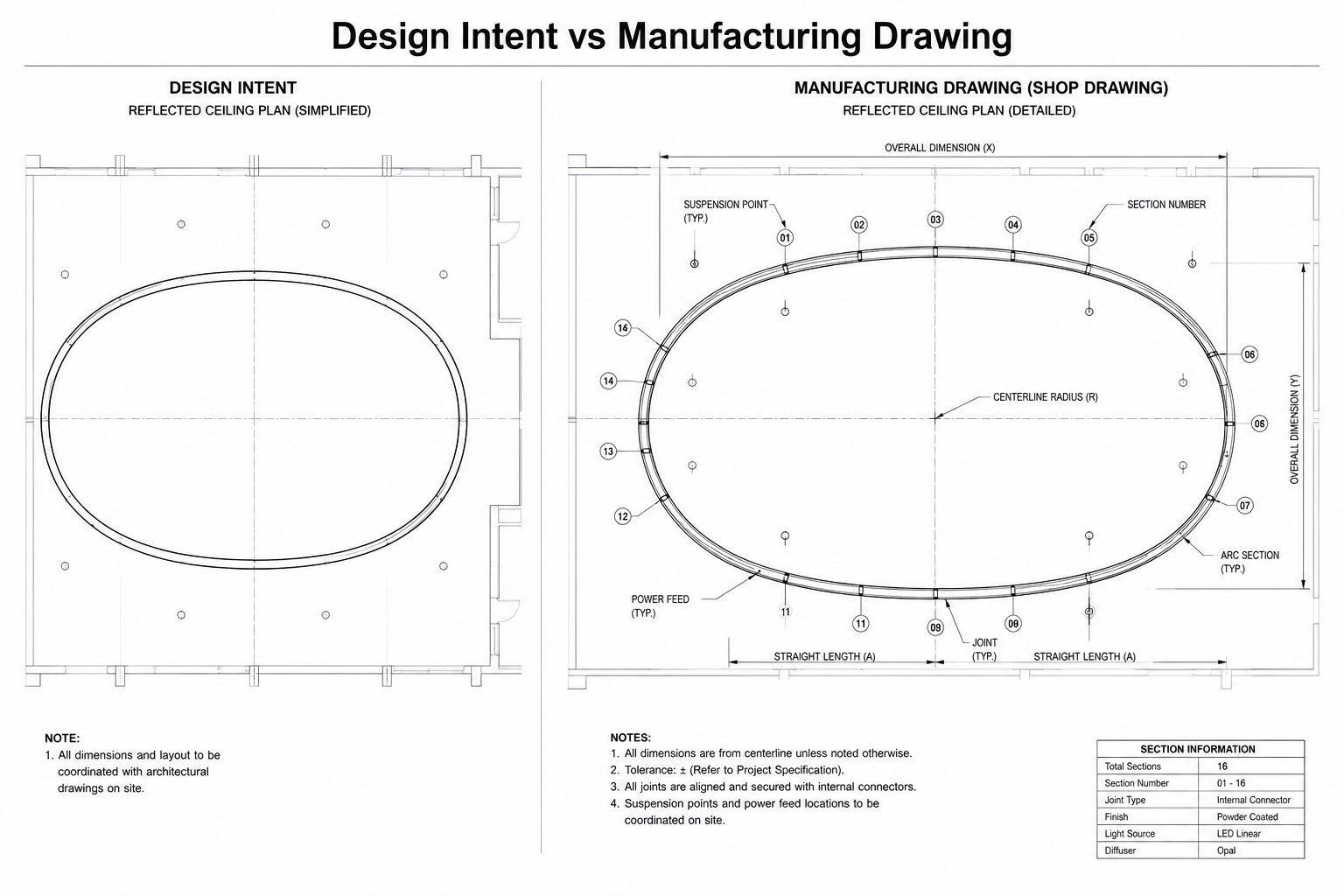
Figure 2. A design-intent RCP must be converted into a controlled shop drawing with dimensions, radii, joints, suspension points, feeds and section numbers.
◆ Centerline Dimensions vs. Overall Dimensions
This is particularly important for curves.
Consider a circular fixture with a 60 mm-wide housing. A 3000 mm centerline diameter is not the same as a 3000 mm outside diameter. The difference changes the bending radius, circumference and final position relative to the ceiling.
A drawing should identify which dimension controls:
- centerline;
- inner edge;
- outer edge;
- luminous opening.
The same rule applies to ovals, arcs and curved wall-wash features.
◆ Stage 3: Choose the Profile and Mounting Platform
The profile is the mechanical backbone of the system. Selection should consider:
- required visible width;
- housing depth;
- LED board width;
- thermal performance;
- diffuser or lens;
- driver space;
- mounting hardware;
- bending feasibility;
- structural rigidity;
- section joining;
- ceiling interface.
A profile that works for a straight suspended run may not be suitable for a tight-radius curve. Likewise, a profile that bends well may not have enough internal volume for an integral driver.
◆ Suspended Projects
For suspended systems, define:
- suspension cable length;
- suspension-point spacing;
- power canopy;
- feed cable;
- direct or direct/indirect output;
- ceiling attachment;
- anti-rotation requirements where relevant.
Large shapes may require more suspension points than a standard straight luminaire.
◆ Recessed and Trimless Projects
For recessed systems, define:
- cutout;
- body depth;
- visible aperture;
- ceiling thickness;
- flange;
- trimless mud-in detail;
- bracket position;
- driver access.
Do not assume the contractor can “adjust the opening on site.” On a long continuous run, inconsistent cutouts can create visible alignment problems.
◆ Surface-Mounted Projects
For surface systems, coordinate:
- bracket spacing;
- substrate;
- cable entry;
- junction-box position;
- fixture-to-ceiling tolerance;
- access for fasteners.
◆ Stage 4: Engineer the Light, Not Only the Housing
A custom housing does not automatically create a good luminaire. The optical and electrical system should be selected based on project performance.
▸ LED module
Review:
- voltage;
- power per meter;
- LED pitch;
- PCB width;
- CCT;
- CRI;
- color consistency;
- maximum run length.
▸ Diffuser or lens
Review:
- material;
- transmission;
- diffusion;
- dot-free requirement;
- beam angle;
- asymmetric or batwing distribution where needed;
- compatibility with curved sections.
▸ Driver
Review:
- input voltage;
- output voltage/current;
- power rating;
- dimming protocol;
- minimum load;
- driver location;
- access for maintenance.
▸ Thermal design
Higher wattage is not always better. LED performance and lifetime depend on thermal conditions. The aluminum profile, LED board and operating environment must be considered together.
◆ Stage 5: Convert the Lighting Design Into Electrical Zones
A continuous luminous line can contain multiple electrical circuits.
The project team should define:
- feed locations;
- driver groups;
- maximum load per driver;
- dimming zones;
- emergency sections;
- RGB/RGBW control zones;
- sensor zones.
This is particularly important for DALI, 0-10 V and DMX systems.
Current IES lighting-control guidance treats controls as a system involving design, documentation, equipment, protocols, commissioning and functional testing. For a custom luminaire package, the driver and control architecture should therefore be documented before production rather than left to site improvisation.
◆ Stage 6: Section the Fixture for Manufacturing and Shipping
A large custom luminaire is usually a kit of coordinated sections.
Section length is influenced by:
- extrusion stock length;
- bending process;
- machining;
- finishing;
- diffuser length;
- freight restrictions;
- carton/crate size;
- site access;
- installer handling.
▸ Example: a large circle
A large-diameter circle may be divided into three, four or more arc sections. Each section should be identified in the shop drawing and on the packaging. The design should specify:
- arc number;
- orientation;
- joint location;
- suspension point;
- electrical connector;
- diffuser section.
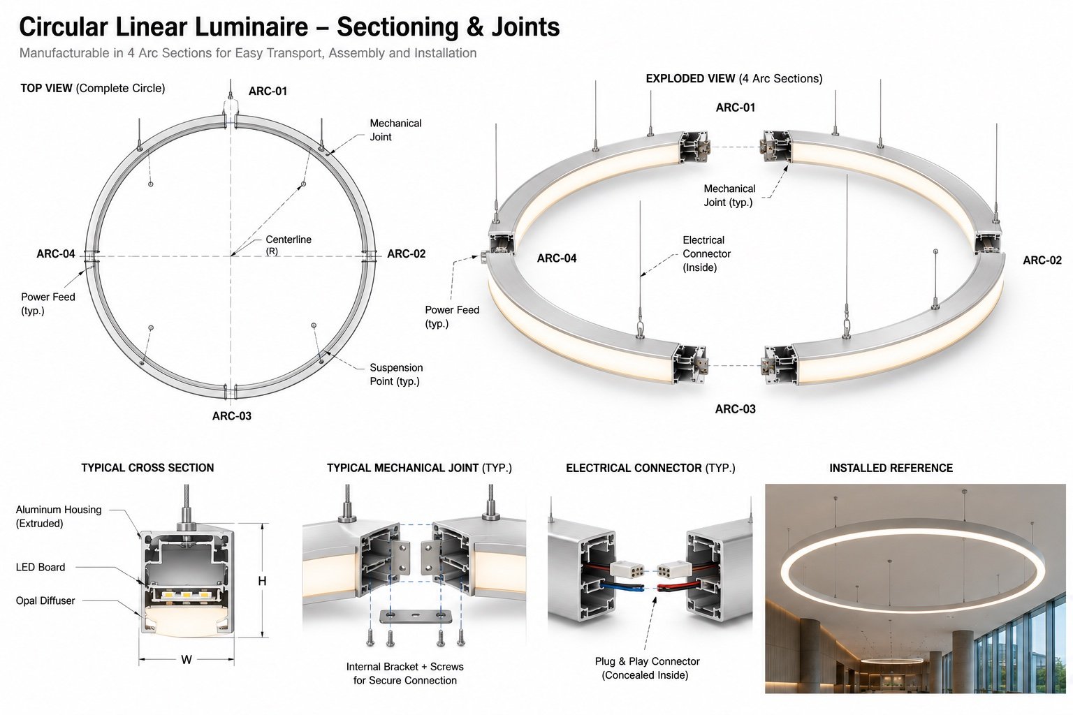
Figure 3. A large circular luminaire engineered as transportable arc sections with planned joints, suspension points and concealed electrical connectors.
▸ Example: a long recessed run
A 20-meter run might be divided into repeatable straight sections. The manufacturer should coordinate mechanical joiners, LED continuity, diffuser joints and feed locations.
◆ Stage 7: Engineer the Joints
Joints are one of the most visible indicators of quality in architectural linear lighting. A joint includes several separate interfaces:
- aluminum housing;
- LED board or wiring;
- diffuser/lens;
- mechanical alignment;
- surface finish.
A housing can be mechanically connected while the luminous line still shows a dark gap. Conversely, a diffuser can appear continuous while the aluminum housing is misaligned.
The shop drawing should show how sections connect and what the installer must do to achieve alignment.
◆ Stage 8: Produce Shop Drawings Before Mass Production
Shop drawings translate the architect’s design into production instructions. For a large custom project, shop drawings should typically show:
- project/fixture reference;
- overall geometry;
- profile cross-section;
- section numbers;
- individual lengths;
- radii;
- angles;
- mounting points;
- feed points;
- driver locations;
- connector details;
- finish;
- diffuser/lens;
- LED specification;
- control type.
IES LP-1-24 includes construction documentation and quality assurance within the lighting-design process, while IES TM-32-24 addresses standardized luminaire parameters for BIM. Both reinforce the value of consistent technical documentation between design and construction teams.
◆ Stage 9: Prototype the Highest-Risk Detail
Not every project needs a full-size mockup. But high-risk details should be validated before mass production. Possible samples include:
- a 500-1000 mm straight section;
- a recessed ceiling-interface sample;
- one corner;
- one curved section;
- a housing/diffuser color sample;
- a complete driver and dimming sample;
- a full-size prototype of a critical shape.
The sample should answer a specific question. For example: Is the diffuser dot-free? Does the trimless flange work with the ceiling? Does the selected radius bend cleanly? Does the dimming system reach the
required low level?
◆ Stage 10: Lock the Approved Specification
After approval, create a controlled specification that identifies the production baseline. Typical locked items include:
- profile revision;
- drawing revision;
- dimensions;
- LED board;
- driver;
- diffuser/lens;
- finish;
- mounting kit;
- control method;
- labels;
- packaging.
Changes after this point should be treated as engineering changes because they may affect material already purchased or manufactured.
◆ Stage 11: Fabrication
Depending on the product, fabrication can include:
- cutting;
- mitering;
- drilling;
- countersinking;
- punching;
- CNC machining;
- bending/forming;
- welding;
- deburring;
- surface preparation.
For custom linear systems, repeatability matters. A project may contain dozens or hundreds of sections that must assemble into a coherent architectural pattern.
◆ Stage 12: Surface Finishing
Common aluminum finishes include powder coating and anodizing. The project should define:
- finish type;
- color reference;
- gloss level;
- texture;
- acceptable color tolerance;
- whether internal visible surfaces require the same finish.
Curved and welded components may require additional surface preparation to achieve a consistent final appearance.
◆ Stage 13: Assembly
Assembly typically combines:
- aluminum housing;
- LED boards;
- internal wiring;
- connectors;
- drivers;
- diffusers/lenses;
- end caps;
- suspension or mounting hardware.
For project kits, the assembly strategy should also consider what should be factory-assembled and what should remain separate for installation.
◆ Stage 14: Testing and Quality Control
Testing should match the project risk and specification. Possible checks include:
- dimensional inspection;
- visual finish inspection;
- electrical safety checks;
- power measurement;
- functional lighting test;
- dimming test;
- color/CCT verification;
- thermal testing;
- photometric testing;
- IP testing where applicable;
- aging/burn-in according to the manufacturer’s process;
- fit-up test between adjoining sections.
Photometric testing is especially valuable when a custom optical configuration changes the distribution from a standard product.
◆ Stage 15: Pre-Assembly for Complex Shapes
For large circles, ovals or patterns, factory pre-assembly can identify
problems before shipment. A pre-assembly check can verify:
- overall geometry;
- section numbering;
- joint alignment;
- mechanical connectors;
- suspension positions;
- electrical continuity.
The entire system does not always need to remain assembled; it can be checked, documented, disassembled and packed as numbered sections.
◆ Stage 16: Packing and Identification
Packaging is part of the engineering solution. Each section should be easy to identify on site. Useful labels include:
- project name;
- fixture tag;
- shape/run number;
- section number;
- quantity;
- orientation where needed.
A packing list should connect the cartons or crates to the shop drawing. For long profiles and large curved sections, protective packaging should prevent:
- bending;
- twisting;
- diffuser scratching;
- finish damage;
- joint deformation.
◆ Stage 17: Installation Documentation
Installation drawings should be simpler than manufacturing drawings. An installer needs to know:
- which section goes where;
- assembly order;
- suspension or bracket locations;
- feed points;
- connector method;
- driver location;
- diffuser installation sequence;
- leveling/alignment procedure.
A numbered diagram is often more useful on site than a long written instruction.
◆ Stage 18: Site Installation
The recommended sequence depends on the mounting method.
▸ Suspended system
A typical sequence is:
- locate ceiling fixing points;
- install suspension hardware;
- hang and roughly level housing sections;
- connect mechanical joints;
- connect wiring;
- align and level the full run;
- install or finish diffusers;
- energize and test.
▸ Recessed/trimless system
A typical sequence is:
- verify ceiling opening and framing;
- install housing or trimless channel;
- coordinate ceiling finishing;
- install electrical components;
- connect sections;
- install LED/diffuser components as designed;
- test and commission.
The exact sequence should follow the approved product design.
◆ Stage 19: Commissioning
Commissioning is not limited to turning the lights on. For controlled systems, verify:
- dimming response;
- zoning;
- scene settings;
- sensor behavior;
- control addresses;
- emergency function where applicable;
- RGB/RGBW programming;
- absence of flicker or incompatibility problems within the specified operating range.
◆ The Most Common Failure Points in Custom Projects
▸ Incomplete dimensions
A concept drawing is released without exact radii, ceiling openings or elevations.
Prevention: require coordinated shop-drawing approval.
▸ Confusing radius definitions
The architect gives an outside diameter while the manufacturer assumes a centerline diameter.
Prevention: label the controlling geometry.
▸ Unplanned joints
Section boundaries are decided only after production or packing constraints become apparent.
Prevention: agree on the section plan during engineering.
▸ Driver access is blocked
Remote drivers are placed above inaccessible ceilings.
Prevention: coordinate maintenance access before approval.
▸ Diffuser joints do not match housing joints
The luminous line develops unexpected seams.
Prevention: show diffuser segmentation separately.
▸ Controls are specified too late
The driver has already been selected before DALI, 0-10 V or DMX requirements are confirmed.
Prevention: lock the control protocol with the electrical
specification.
▸ Installation tolerance is ignored
A long run is designed with no allowance for real ceiling variation.
Prevention: coordinate site dimensions and provide an installation strategy appropriate to the architecture.
◆ What Should Be Approved Before Production?
Use this project gate:
- final RCP or controlled dimensions;
- profile cross-section;
- mounting method;
- overall geometry;
- section lengths;
- radii and angles;
- joint locations;
- suspension/bracket locations;
- LED specification;
- diffuser/lens;
- driver;
- control method;
- voltage;
- finish;
- labels;
- packing concept;
- applicable test/certification requirements.
If one of these affects fit, safety or appearance, it should not remain ambiguous.
◆ How to Compare Custom Linear Lighting Suppliers
Price per meter alone is a poor comparison for engineered projects. Evaluate whether the supplier can support:
- drawing review;
- profile and optical selection;
- bending and machining;
- photometric data;
- driver/control integration;
- prototypes;
- coordinated shop drawings;
- factory pre-assembly;
- quality documentation;
- project packing;
- technical support during installation.
The objective is not simply to buy aluminum and LEDs. It is to reduce the risk between architectural intent and installed result.
◆ How Felix Electric Approaches Custom Commercial Projects
Felix Electric supports standard and custom linear lighting products with in-house and supply-chain capabilities covering profile production, plastic extrusion, CNC machining, bending, cutting, assembly and testing.
For custom projects, the practical starting point is the drawing. The engineering team can review geometry, mounting, profile selection, optical configuration, sectioning and manufacturing feasibility before production.
For the most efficient review, contact Felix Electric and provide the RCP/CAD file, fixture schedule, quantities, mounting details, voltage, CCT/CRI, control method, finish and target delivery schedule.
◆ Frequently Asked Questions
▸ How early should a custom linear lighting manufacturer be involved?
Ideally before construction details are fully locked. Early involvement allows the profile dimensions, ceiling opening, driver access, sectioning and mounting method to be coordinated before they become expensive site constraints.
▸ Can a manufacturer quote from a reflected ceiling plan only?
A budget quotation may be possible, but final production usually requires dimensioned geometry, cross-sections, quantities and electrical requirements.
▸ How are large circles and ovals shipped?
They are normally divided into arc sections sized for manufacturing, packing and site handling. The sections should be numbered and matched to an assembly drawing.
▸ Can a continuous linear light have no visible joints?
Joint visibility can be reduced, but the specification must distinguish housing joints from diffuser/luminous joints. Very long continuous diffusers may be limited by material, extrusion, transport and installation constraints.
▸ Should the driver be inside the linear profile or remote?
Both approaches are possible. Integral drivers simplify some installations but require sufficient housing space and service access. Remote drivers can reduce profile size but need an accessible remote location and appropriate wiring.
▸ What is the best file format for custom lighting drawings?
DWG/DXF files are useful for geometry, while dimensioned PDFs are useful for controlled review and approval. BIM data can also support coordination when available.
▸ What should be tested before shipment?
At minimum, verify dimensions, appearance, electrical function and section compatibility. Depending on the project, also verify dimming, thermal performance, photometry, IP performance or other specified requirements.
▸ How can installation errors be reduced?
Use section numbering, clear packing labels, assembly drawings, defined feed points and pre-assembly checks for complex shapes. The installer should not have to infer the order of parts.
◆ Conclusion
The success of custom linear lighting is determined long before the fixture reaches the ceiling.
A reliable project moves through a controlled sequence: collect complete drawings, resolve geometry, select the mechanical platform, engineer the LED/optical/driver system, define electrical zones, plan sections and joints, approve shop drawings, validate high-risk details, manufacture, test, pre-assemble where appropriate, pack by section and install from a clear assembly plan.
For large commercial projects, this workflow reduces redesign, site cutting, mismatched sections, control incompatibility and visible alignment problems.
Project CTA: Send Felix Electric your RCP, CAD/PDF drawings, fixture schedule, quantities, mounting details and performance requirements. We can review the geometry, section plan and manufacturing approach before quotation.