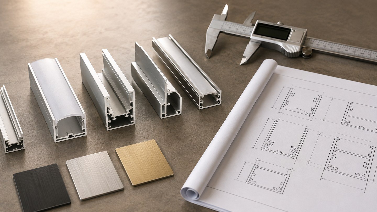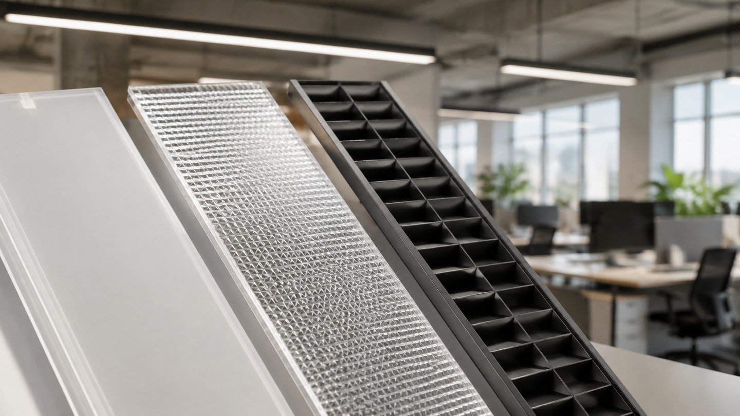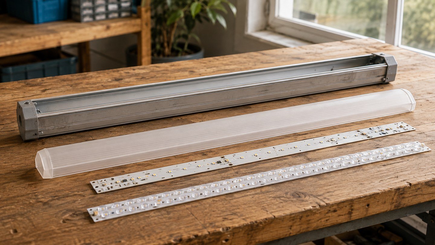
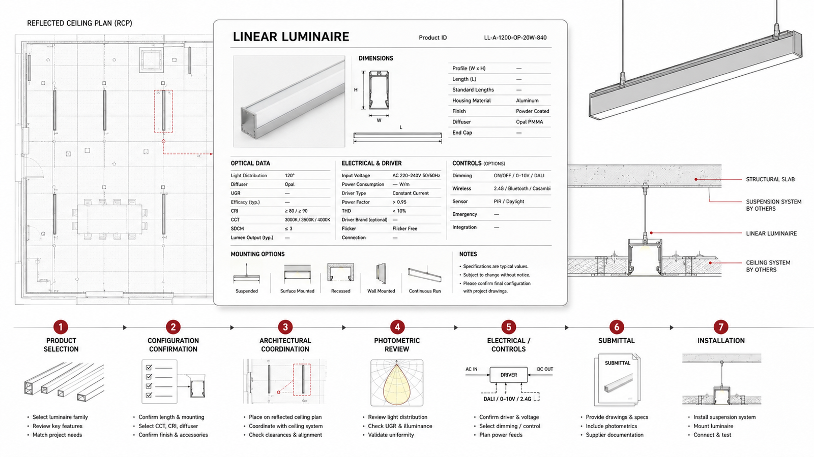
A linear luminaire can look resolved on a reflected ceiling plan long before it is ready to be specified.
The drawing may show a clean line, a fixture tag and an overall length. Then coordination begins. The architect needs the actual ceiling opening. The electrical engineer wants to know where the driver sits and which control protocol has been selected. The lighting designer needs photometry for the specified optic, not a generic file for the product family. On a continuous run, somebody has to establish where the sections divide and where power enters. If the line becomes a circle or a curve, even the basic geometry can become ambiguous: outside diameter, inside diameter or centerline?
These are not unusual exceptions. They are what happens when a luminaire moves from design intent into a building.
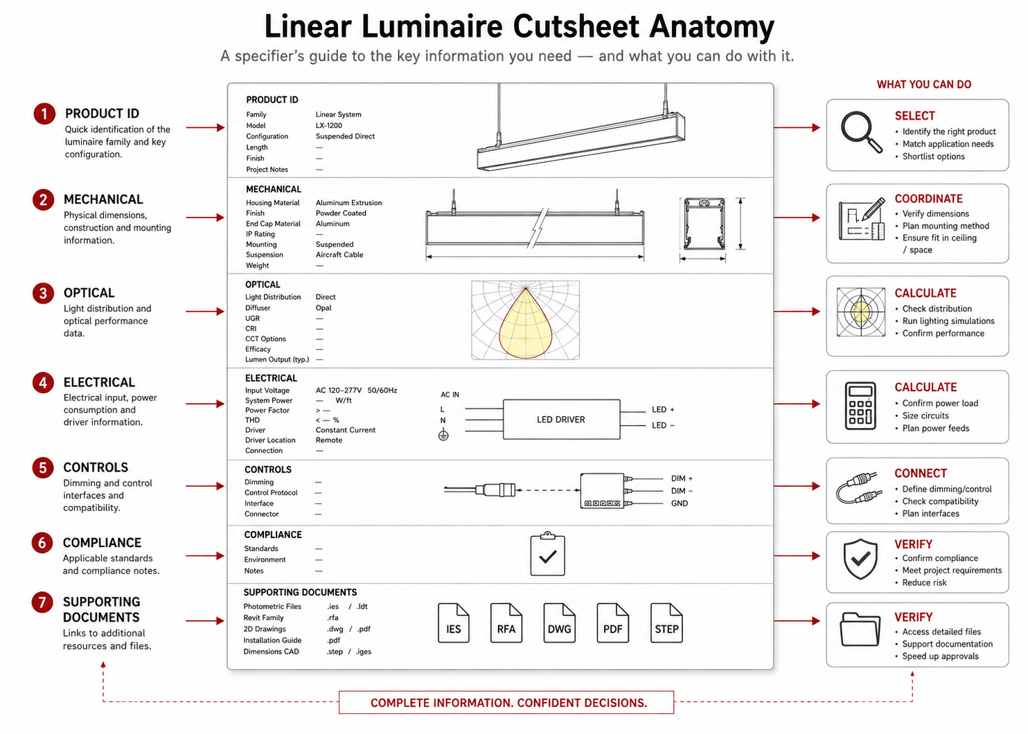
A useful linear luminaire cutsheet has to survive that transition. It does not need to contain every drawing, test report or installation instruction associated with the product. It does need to identify the configuration being specified, show the information that materially affects selection and coordination, and make clear where the rest of the technical record can be found.
For a standard individual fixture, that may be straightforward. For a recessed continuous run, a large suspended ring or a custom curved system, the cutsheet is usually the first layer of a larger documentation package.
Quick Answer
A professional linear luminaire cutsheet should let a specifier answer five questions:
- Which exact product configuration is being proposed?
- What physical space and architectural interface does it require?
- What optical performance belongs to that configuration?
- How is it powered, controlled, mounted and accessed?
- Which additional documents are still required for coordination, submittal or installation?
Not every field is mandatory for every luminaire. A surface-mounted fixture does not need a ceiling cutout. A standard straight product may not need a segment map. TM-30, IK or project-specific suspension coordinates may be relevant in one project and unnecessary in another.
The stronger principle is this: the documentation should follow the product and the project risk, rather than forcing every luminaire into the same generic datasheet template.
A Cutsheet Is Part of a Technical Record, Not the Whole Record
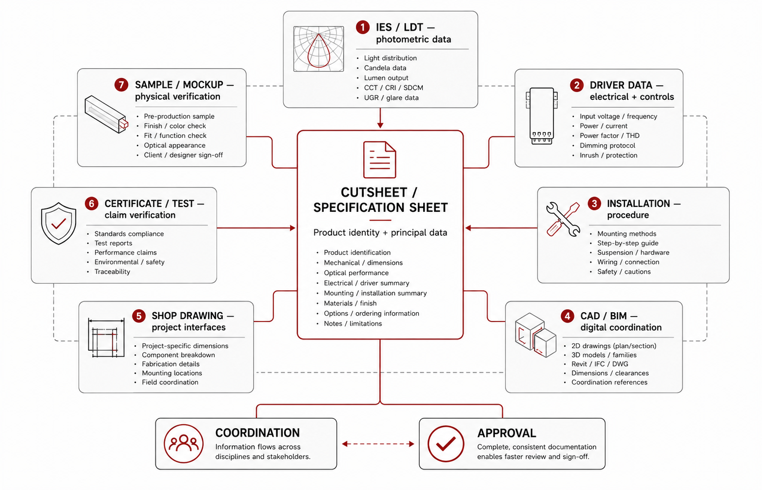
The word cutsheet is often used interchangeably with specification sheet or technical datasheet. In practice, it sits between two different kinds of information.
On one side is the brochure: useful for presenting the family, applications and appearance, but rarely sufficient for technical approval. On the other is the deeper project record—photometric files, driver documentation, installation instructions, CAD/BIM resources, certificates and, where required, project-specific shop drawings.
Trying to compress all of that into one PDF does not necessarily make the documentation better. It can make the information harder to trace.
| Document | What it should resolve |
|---|---|
| Cutsheet / specification sheet | Which luminaire and configuration are being specified, with principal mechanical, optical and electrical data |
| IES / LDT | Photometric distribution for the relevant tested or modeled condition |
| Driver datasheet | Detailed electrical and control characteristics |
| Installation instructions | Mounting, assembly, wiring access and installation procedure |
| CAD / BIM | Digital architectural and MEP coordination where available |
| Shop drawing | Project-specific dimensions, joints, feeds, suspensions and interfaces |
| Test report / certificate | Evidence supporting a stated performance or compliance claim |
| Sample / mockup | Physical verification where drawings and data do not fully resolve appearance or integration |
The cutsheet is therefore best understood as the entry point to the technical record. Its job is not to replace every supporting document. Its job is to make the selected product traceable through them.
Start With the Configuration, Not the Product Family
A product family can contain several profile sizes, outputs, optics, finishes, colour temperatures and control options. Naming the family does not yet establish what will be ordered, coordinated or installed.
The cutsheet should therefore provide a clear route from family to configuration. Depending on the manufacturer, that may be an ordering code, a configured model number or a selection table that shows the chosen values without forcing the reviewer to infer them.
Felix’s Full Ring Pendant documentation, for example, uses an ordering sequence that identifies the model together with CCT, CRI, finish, light direction, dimming and input voltage.
That matters because downstream information can change with the selection. A different optic can require different photometry. A different control protocol can mean a different driver. A different mounting condition can change the hardware and architectural preparation.
A reviewer should be able to answer a simple question without cross-reading three unrelated PDFs:
Which configuration of this family are we actually approving?
Document revision and date are useful for the same reason. A technically correct sheet can still be the wrong sheet if it describes an obsolete configuration or earlier product revision.
Dimensions Become Useful When They Describe an Interface
Width, height and length belong on a cutsheet, but their value is not in filling three cells of a table. They matter because something else has to fit around them.
For a suspended luminaire, profile dimensions establish physical scale and can influence sightlines, ceiling clearance and suspension geometry. For a recessed system, the coordination becomes more sensitive: housing width, visible aperture and ceiling cutout are not necessarily the same dimension. A nominal width without the relevant interface dimension can leave the ceiling contractor to infer the opening.
Useful mechanical information may therefore include:
- housing or profile width and height;
- overall or nominal fixture length;
- visible luminous aperture;
- required cutout or opening where applicable;
- principal housing and optical materials;
- finish;
- weight where support or handling is affected;
- end conditions that change the visible or installation dimension.
Felix’s Full Ring Pendant documentation identifies a W51 × H91 mm profile, 6063 extruded aluminium construction, PMMA optical material and suspension mounting.
Curved and circular products need an additional discipline: the dimensional reference itself must be defined. A ring described only as “3 m diameter” is not fully resolved if the drawing does not state whether that means outside diameter, inside diameter or centerline diameter.
Continuous runs create a similar distinction between architectural length and manufacturable length. The RCP may show one uninterrupted line; production, transport and installation may require several sections.
The dimension is useful only when the project team knows what it governs.
“Suspended” Is a Mounting Category, Not an Installation Detail
Mounting descriptions can be technically correct and still leave the project unresolved.
A large pendant ring may indeed be suspended. That tells the specifier very little about how many suspension points are involved, where power enters, how the canopy is arranged or whether the fitting is shipped as one piece or several.
The Felix ring documentation illustrates the difference. Its model table identifies profile segment quantity, diffuser segment quantity, weight and suspension-point count for different ring sizes. Those fields begin to describe how the object actually meets the building.
A recessed system asks different questions. What is the ceiling interface? Is there a required opening? Does the housing need access from above? Where is the driver? Can it still be serviced after the ceiling closes? Does the interface change between gypsum board, acoustic ceiling and joinery?
The cutsheet does not need a construction drawing for every condition. It should make the applicable mounting method unambiguous and point to the detail that resolves the interface.
That is the point at which product information begins to become architectural coordination.
Photometry Has to Belong to the Luminaire Being Specified
Lighting data can look precise while still being too generic for a project decision.
A cutsheet may state wattage, delivered lumens, efficacy, CCT, CRI and beam angle. Those numbers are useful only if the reviewer understands which configuration they describe.
The Felix ring documentation, for example, distinguishes direct and indirect power and lumen values and identifies CCT, CRI and nominal beam angle. It also notes that final output may vary with length, diffuser tolerance and test conditions.
That qualification is more valuable than an apparently universal number. If a family contains several lengths, optics or outputs, one generic performance table may not represent every possible configuration.
For calculated projects, the cutsheet should therefore make it easy to identify the relevant optical condition and locate the appropriate IES or LDT file where available. The point is not simply to prove that “photometry exists”; it is to know that the photometry is sufficiently representative of the product under review.
CRI, TM-30 and UGR Need Different Treatment
Not every lighting metric belongs in the same category.
CRI is commonly included because it describes a colour-rendering characteristic of the source or luminaire configuration. Where colour quality needs deeper evaluation, TM-30 data may be useful or required by the project. That does not make TM-30 a universal requirement for every linear-lighting cutsheet.
UGR requires still more caution. A single glare figure can be attractive in a comparison table, but glare evaluation depends on distribution, room geometry, layout and viewing conditions. Where visual comfort is a design priority, the documentation should provide enough photometric information for the actual application to be evaluated rather than treating one number as a universal property of the product.
The cutsheet should support analysis, not replace it.
Electrical Data Should Describe the Supplied Condition
A luminaire eventually has to connect to a power system, and the driver is part of that interface.
The basic electrical block should identify the input voltage and relevant power data. It should also make clear, where applicable, whether the driver is integral or remote and provide enough driver identification for compatibility, access and maintenance to be reviewed.
Felix’s ring document states AC120–277V input, 0–10V dimming and a built-in ARCATA driver for the documented product.
On a straightforward pendant, that may answer much of the initial electrical question. On a long continuous system or large feature installation, it may not. Driver grouping, remote-driver location, feed arrangement and service access can become project-specific coordination issues.
The rule is simple: state what is actually supplied for the selected configuration, not every electrical option the family might theoretically support.
“Dimmable” Is Not a Control Specification
The same discipline applies to controls.
A cutsheet that says only “dimmable” still leaves the most important question unanswered: dimmable by what system?
The selected protocol might be 0–10V, DALI, phase dimming or another control method. The relevant driver has to support it, and the building controls team has to know what interface is being coordinated.
Where dimming is part of the order code, the selected method should be visible in the configuration. Where additional control modules, gateways, emergency functions or sensors are required, they should be identified through verified supporting documentation rather than implied by a generic product-family statement.
This is one area where a concise cutsheet can be stronger than a crowded one. The document does not need to reproduce the entire driver manual. It needs to tell the reviewer exactly which control condition applies and where the detailed driver data can be found.
Ratings Only Mean Something in Context
IP, IK, safety listings, operating conditions and warranties are useful only when their scope is understood.
An IP rating can help establish environmental suitability, but it does not answer every regulatory question. A certification may apply to a specific model, size, component arrangement or market; it should not automatically be extended to every configuration in a family.
For international B2B projects, the cutsheet should therefore distinguish between:
- a verified product characteristic;
- an available option;
- a project- or market-specific compliance requirement;
- a claim that still requires supporting certification or test evidence.
Felix’s documented ring example identifies IP20 and a five-year warranty. Those statements should be read as characteristics of the documented product, not as evidence that every Felix configuration carries the same rating or approval.
A professional cutsheet makes compliance easier to verify without making the claim broader than the evidence.
The Continuous Run Is Where a Conventional Cutsheet Starts to Struggle
A standard fixture can often be described as a discrete object.
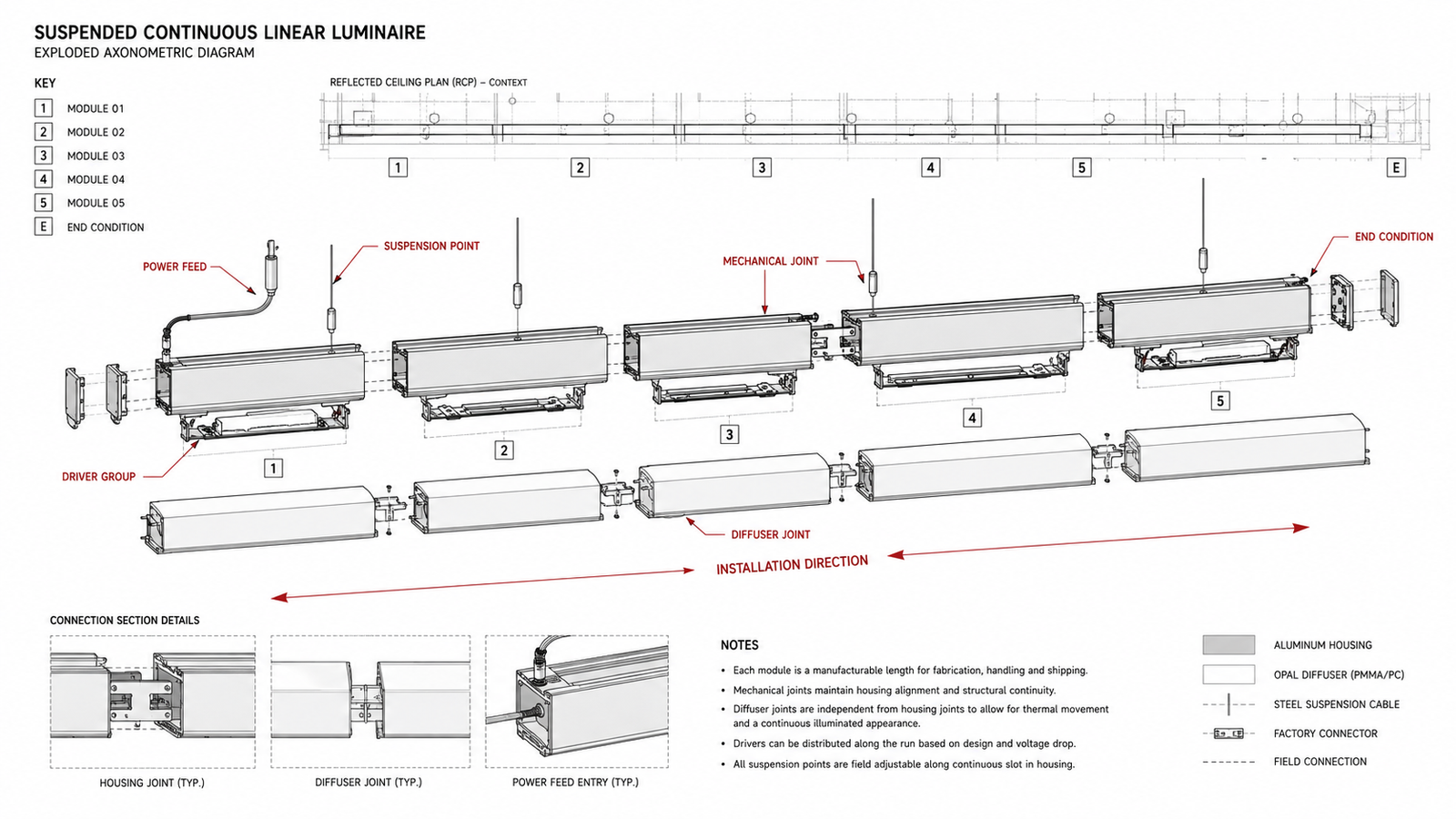
Continuous linear lighting is different. Architecturally, the object may be one line. Manufacturing and installation may divide it into profiles, diffusers, LED boards, drivers, joiners, feeds and mounting points.
That difference is easy to hide on an RCP. It becomes impossible to ignore on site.
Imagine a 12 m suspended run divided into five manufacturable sections. The overall length does not tell the installer where the joints occur. A power requirement does not identify the feed position. “Suspended” does not establish the suspension locations. A driver specification does not show how drivers are grouped or where they remain accessible.
For a continuous system, the technical package may therefore need to resolve:
run length → module lengths → joint positions → power feeds → driver grouping → suspension or mounting locations → end conditions → assembly sequence.
Some of that information may be suitable for the standard cutsheet. Much of it may belong in installation documentation or a project-specific shop drawing.
The important point is that the project team can see the boundary. A catalogue option such as “continuous run” should not conceal the coordination work required to turn that option into a buildable system.
Curves and Rings Turn Product Data Into Project Geometry
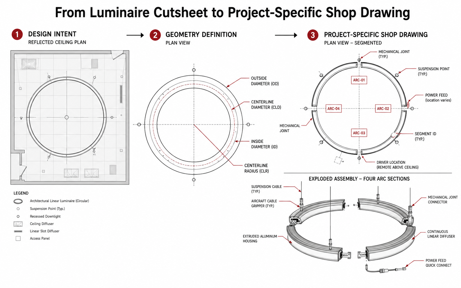
Custom geometry exposes the limits of generic catalogue documentation even more quickly.
A straight linear luminaire may be defined through family, length and mounting. A curved run adds radius. A ring adds diameter. An oval can require several geometric references. Once the size exceeds practical manufacturing, packaging or transport constraints, segmentation follows.
Then the project starts asking questions that do not exist on a standard straight fixture:
- What dimension governs production: OD, ID or centerline?
- Where does each section start and stop?
- Where will the joints be visible?
- Where does power enter?
- How many suspension points are required, and where?
- How are the sections identified for field assembly?
- Where are the drivers, and how are they accessed?
Felix’s ring documentation already provides model-specific segment quantities, weight, suspension-point counts and dimensional drawings. For a project-specific circle, oval or freeform feature, however, those generic product fields may still need to be translated into a shop drawing that fixes the geometry, segmentation, joints, feeds and mounting locations against the actual project.
This is also where a sample or mockup can become useful—not as an automatic requirement, but where drawings and calculations leave meaningful uncertainty around a joint, diffuser continuity, finish, brightness relationship or architectural interface.
The cutsheet can define the product platform. The project drawing has to define the project.
What Is Often Missing Is Not Data, but Traceability
The weakest cutsheets are not always the ones with the fewest numbers.
Often, the information exists but the relationship between the pieces is unclear. A product family is shown, but the selected configuration is not. An IES file exists, but the sheet does not identify which optic it represents. The housing width is stated, but the ceiling opening is not. Dimming is offered, but the selected driver is unidentified. A custom-length run is possible, but no document shows how it will be segmented or fed.
These gaps create decisions downstream.
The architect assumes the opening. The electrical engineer assumes control compatibility. The contractor chooses a feed position. The installer discovers a joint where the design team did not expect one.
By then, a documentation gap has become a coordination issue.
A strong cutsheet therefore does more than carry data. It helps the reviewer trace each important claim back to the selected configuration and forward to the next required document.
Specifier’s Linear Luminaire Cutsheet Checklist
This checklist separates broadly useful information from fields that become necessary only when the application demands them.
| Category | What to check | Why it matters | Priority |
|---|---|---|---|
| Product identity | Manufacturer, family, model | Establishes what is under review | Core |
| Configuration | Output, CCT, CRI, optic, finish, mounting, controls as applicable | Prevents family-level data being mistaken for selected-product data | Core |
| Ordering logic | Ordering code or configured model | Connects specification to procurement | Core |
| Revision | Current document date/revision | Reduces obsolete-data risk | Core |
| Mechanical | Housing/profile dimensions, length, construction | Spatial coordination | Core |
| Aperture / cutout | Visible opening and required ceiling opening | Ceiling/interface coordination | Conditional |
| Weight | Fixture or section weight | Support, handling and installation | Conditional |
| Mounting | Applicable mounting system and detail reference | Building interface | Core |
| Photometric summary | Output, power, distribution/optic | Performance review | Core |
| IES / LDT | File for relevant configuration where available/required | Lighting calculation | Conditional / often core for calculated projects |
| Light quality | CCT, CRI; additional verified colour data where needed | Visual/specification requirements | Core / Conditional |
| Electrical | Input voltage, power, driver arrangement | Electrical coordination | Core |
| Controls | Exact selected dimming/control method | Controls compatibility | Core when controls apply |
| Environment | IP/IK or operating conditions where relevant | Environmental suitability | Conditional |
| Compliance | Applicable certification/listing evidence | Project and market approval | Project-specific |
| Continuous run | Module lengths, joints, feeds, driver grouping, end conditions | Manufacturing/installation coordination | Project-specific |
| Curved/ring geometry | Radius/diameter basis, segment map, joints, suspensions | Project geometry and assembly | Project-specific |
| Supporting documents | Installation, driver data, photometry, CAD/BIM, certificates, shop drawings as applicable | Completes the technical record | Core |
The list is deliberately not reduced to a universal “20 mandatory fields.” Linear lighting changes category as it becomes more integrated, continuous or customised. The documentation has to change with it.
Before Approval, Ask What Is Still Unresolved
The most productive submittal review is not a search for a perfectly populated PDF. It is a search for assumptions.
Does the ordering code describe the configuration shown in the schedule? Does the photometry belong to that configuration? Has the ceiling interface been defined? Does the control method match the selected driver? For a continuous run, are the modules, joints and feeds resolved? For a ring or curve, is the controlling geometry unambiguous?
Then ask one final question:
Which answers belong on the cutsheet, and which require another project document?
That question keeps the cutsheet concise without allowing the technical record to become incomplete.
The Next Step: Machine-Readable Luminaire Data
The documentation problem is increasingly not just whether information exists, but whether it can be transferred consistently between specification, software, procurement and project workflows.
The Universal Luminaire Cutsheet initiative proposes an open, machine-readable structure that can sit alongside familiar PDF and photometric files, with a stronger emphasis on configuration-specific and traceable data. It should be understood as an emerging industry approach, not a universal regulatory requirement.
The underlying direction is relevant even for conventional PDFs: as product families accumulate more optics, drivers, controls and configurable geometry, technical data needs to become more structured, configuration-specific and traceable.
Final Takeaway
A linear luminaire cutsheet begins as product documentation. In a project, it quickly becomes a coordination tool.
The architect uses it to understand the interface. The lighting designer uses it to identify the optical condition. The electrical engineer checks voltage, driver and controls. Procurement relies on the configuration. The installer eventually works from the associated details and project drawings. On a custom system, the manufacturer may have to translate the same specification into section drawings, joint maps and production information.
The document succeeds when all of those decisions still describe the same luminaire.
For a standard linear fixture, that may require a precise cutsheet and the correct supporting files. For a recessed continuous run, a large suspended ring or a custom curve, the documentation will expand into project-specific coordination.
That is not a failure of the cutsheet. It is the point at which product data becomes project information.
For projects involving continuous runs, curved geometry or large feature luminaires, Felix can review drawings and project requirements to identify which product data and project-specific coordination documents are needed before manufacture.
Frequently Asked Questions
What is a lighting fixture cutsheet?
A lighting fixture cutsheet is a technical document that identifies a luminaire or selected configuration and summarises the principal information needed for specification, such as dimensions, mounting, optical performance, electrical characteristics and controls. Detailed photometry, installation procedures and project-specific geometry may be supplied separately.
Does every linear luminaire need an IES file?
Not every application requires a lighting calculation, but projects that depend on photometric analysis generally need suitable photometric data. The important issue is whether the IES or LDT file represents the relevant optic, output and configuration rather than merely belonging to the same product family.
Should UGR be shown on a linear-lighting cutsheet?
Glare information can be useful, but UGR should not be treated as an unconditional product characteristic detached from the application. Luminaire distribution, room geometry, layout and viewing conditions affect glare evaluation, so supporting photometric data remains important where visual comfort is a design requirement.
What information is needed for a continuous linear-lighting run?
Beyond normal product data, a continuous system may need module lengths, joint conditions, power-feed locations, driver grouping, mounting or suspension positions, end conditions and installation sequencing. Some of this information may belong in project-specific drawings rather than the standard cutsheet.
What is the difference between a cutsheet and a shop drawing?
A cutsheet describes the product or configurable product family. A shop drawing applies that product to a specific project, establishing dimensions, geometry, sections, joints, feeds, mounting points and other interfaces that generic product documentation cannot fully define.
What additional information may be required for curved or ring luminaires?
The project may need a defined radius or diameter reference, overall geometry, segmentation, joint positions, suspension points, power feeds and driver arrangement. Complex or highly customised designs may also require project-specific shop drawings, samples or mockups before production.