

To prevent LED hotspots in aluminum profiles, match the LED spacing, the distance to the diffuser and the diffuser design, then check the complete assembly under the intended viewing conditions. Adding an opal cover or choosing a deeper channel can help, but neither change alone guarantees a continuous-looking line.
Start with the pattern you can see. Repeated bright points along the whole run suggest a different investigation from a dark patch at one connector. Once the pattern is clear, compare the relevant components one at a time so you can identify which change improves the result.
What an LED hotspot actually is
A hotspot is a local bright area that lets the viewer perceive the position of an individual LED. It becomes more obvious when the light-emitting points are far apart, the diffuser sits close to them, or the viewing angle exposes the brightest part of the assembly.
The word “spotless” is therefore a visual result, not a standalone material specification. It should describe an agreed sample under stated conditions: the actual strip, output level, profile, diffuser, viewing distance and viewing direction.
Identify the pattern before changing the hardware
A row of bright points repeating along the strip calls for a different investigation from one dark patch at a connector. First record where the pattern occurs: across the whole run, only at a joint, near an end cap, or only when seen in a reflection. Photograph the complete installation as well as the close-up. This prevents a local assembly issue from being treated as a reason to replace every diffuser.
Direct and indirect installations also need different observations. On a shelf edge, the reader may see the diffuser itself. In a cove, the relevant surface may be the wall or ceiling receiving the light. A smooth-looking cover does not tell you whether that reflected line is even. Inspect the surface the occupant actually sees.
Five variables that control visual uniformity
LED pitch. Closely spaced emitting points generally give the optical system less distance to bridge between bright and dark zones. Compare pitch, not only the marketing label or nominal watts per metre.
Optical distance. More separation between the emitting surface and diffuser can give light more room to mix. Profile depth is only a proxy; the useful dimension is the actual distance from the LEDs to the diffuser.
Diffuser behaviour. Compare how well each cover hides individual LEDs and how much useful light the assembly delivers. Clear, frosted and opal covers are different options, so test them with the same strip and profile. For a microstructured optical film, follow its specified installation orientation; an ordinary opal cover should not be assumed to behave the same way when reversed.
Output and control level. A sample viewed at one dimming level may look different at another. Validate the range the project will actually use.
Viewing geometry and interior surfaces. Include direct, oblique and reflected views in the sample review. Record the channel interior and mounting surroundings so the compared samples use the same conditions.
These variables work together. A diffuser that hides the LEDs in one channel may still show individual points when moved closer to the same strip. Changing the LED spacing or emission pattern also changes the comparison. Choose candidate combinations first, then judge them as complete samples; a profile-height figure alone cannot tell you whether the finished line will look uniform.
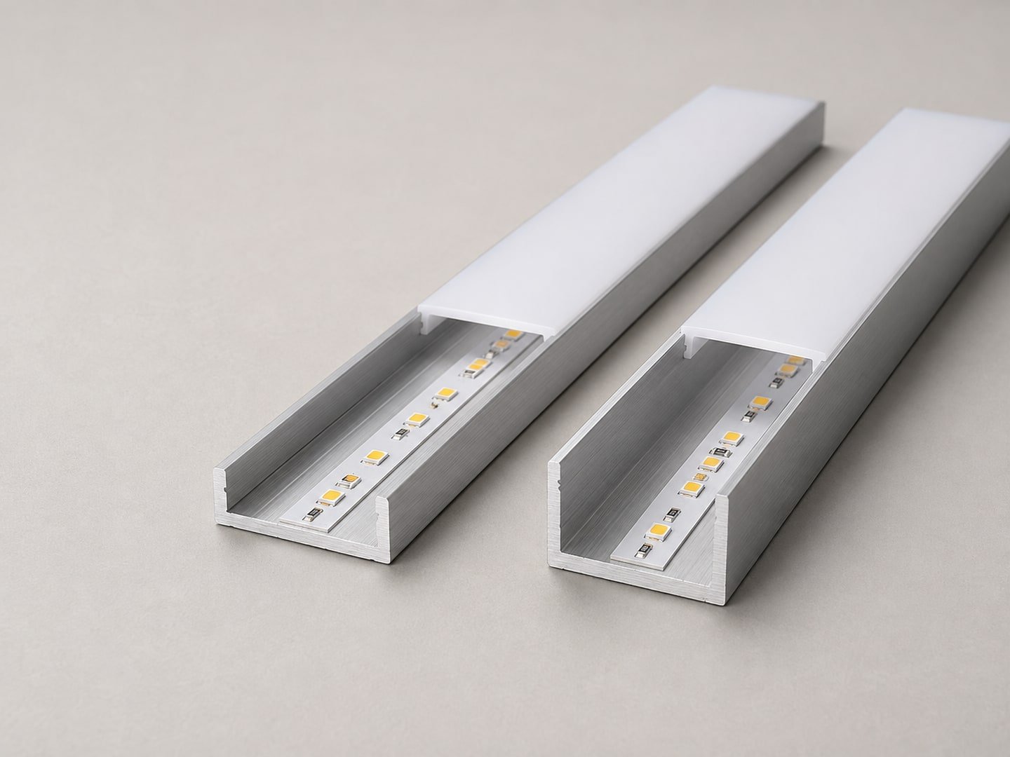
Measure the usable gap, not just the catalogue height
For practical comparisons in this guide, use an emitter-to-cover clearance: mark the light-emitting surface of the installed LED package and the inner face of the fitted diffuser on the section drawing. This is the working reference used here; when using a supplier’s optical-distance data, follow the measurement reference in that document. The mounting bed, strip assembly and cover seating position affect the available clearance, so the outside profile height cannot substitute for the installed geometry.
Keep LED count and emitting pitch separate too. For uniformly spaced single-row emitters, pitch in millimetres is 1,000 divided by the number of emitters per metre: 120 evenly spaced emitters correspond to about 8.3 mm. This is a geometric conversion, not a required profile depth. For a multichannel strip, inspect which emitting zones are active in the intended colour mode; a headline total chip count may not describe that pattern.
When the present strip shows distinct points, include a closer-pitch strip or a COB strip in the sample comparison. Check the full installed run, including cuts, connections and ends, with the proposed cover. A different strip construction is an option to evaluate; its appearance in an uncovered sample does not establish how the finished installation will look.
A practical troubleshooting order
Start by recording the present assembly. Note the strip model or LED pitch, operating power, profile section, LED-to-diffuser distance, diffuser type and the viewing condition where dots appear.
Use one change to answer one question
If the whole length shows repeated points, start with a controlled comparison. Keep one reference sample and change one candidate component at a time. Record what changed and what stayed fixed; otherwise a smoother appearance may come from a different operating level, camera exposure or viewing position.
| Comparison | Question it answers |
|---|---|
| Same strip and cover; different optical gap | Does more separation help this combination? |
| Same profile and strip; different cover | Does the alternative hide the source while providing acceptable delivered light? |
| Same installation; alternative strip construction | Does the emitting pattern improve without creating a different fit, control or output problem? |
| Same sample; direct and intended reflected view | Is the complaint on the luminous aperture, the illuminated surface, or both? |
For a defect confined to a join, compare that area with an uninterrupted section first. Check the spacing between the last LED on one section and the first on the next, any interruption in the emitting run, and how the cover seats. Record what differs before changing the diffuser across the entire installation.
How to validate a “spotless” sample
Use a sample long enough to include joints, feeds or end conditions that may appear in the installation. View it from the project’s normal distance and from any critical oblique angle. Use the intended mounting surface and ambient lighting where practical.
Also confirm that the visually preferred assembly still meets the required output, colour quality, controllability and thermal constraints. Optical uniformity is one requirement within the complete linear-lighting selection process.
Make acceptance repeatable
Write the acceptance conditions beside the sample identifiers: where the observer stands or sits, which operating settings are used, and which joints, corners or ends must be inspected. For example, a sample approved from a standing position may still need a separate check from a nearby seated position. Use the actual project locations and retain the approved assembly for comparison with later deliveries.
Where photographs support approval, keep exposure, white balance, distance and viewpoint consistent between samples, and retain a normal-view image beside the close-up. Photos support the record; the agreed physical sample and required lighting performance still govern the decision.
What to send for a sample review
Provide the profile drawing, LED strip data, diffuser option, target output or control range, mounting detail and photographs showing the critical view. State whether the line will be directly visible, recessed, concealed or viewed in reflection.
Keep final acceptance tied to the physical sample and project conditions. Ask which profile and diffuser options, drawings and sample arrangements are available for the proposed configuration; obtain written confirmation before ordering.
Discuss Your Strip, Profile and Diffuser Sample: describe the assembly and critical viewing condition in your enquiry. Felix can confirm the available options and next steps for the supplied brief.
Featured image: concept illustration.

