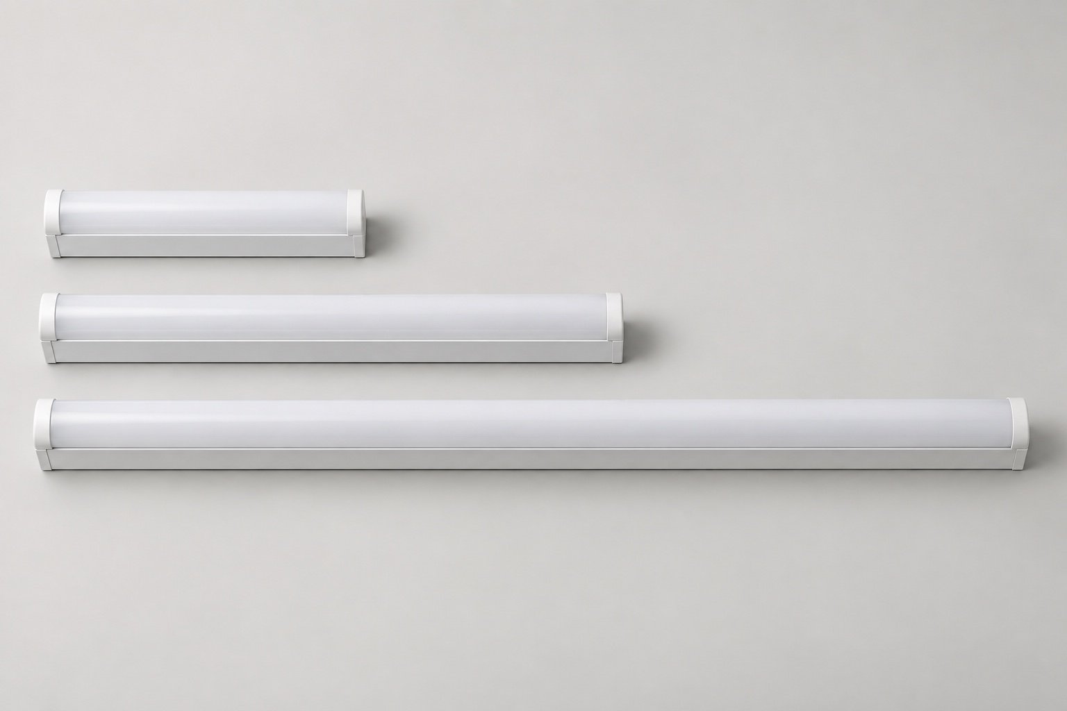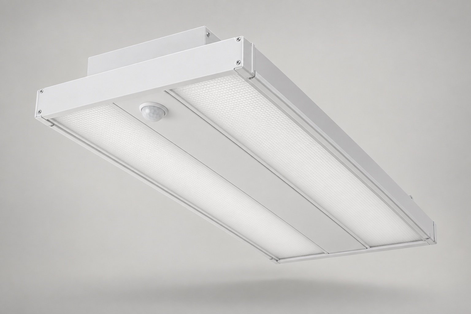
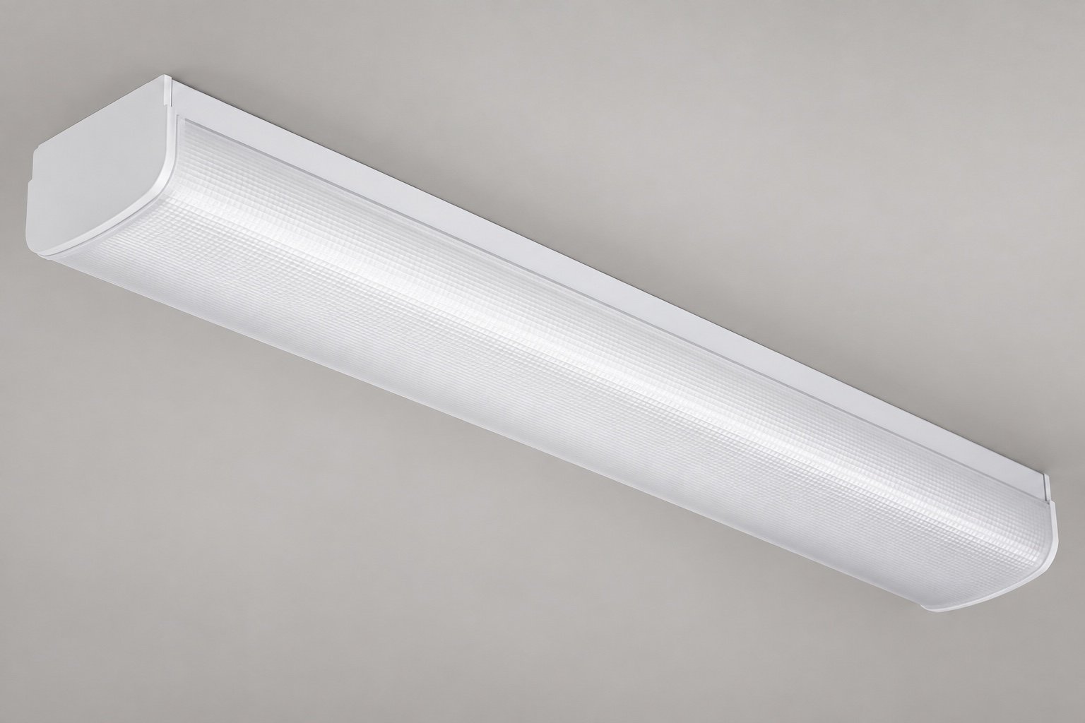
A DLC optical redesign for a linear luminaire has to address both the light leaving the product and where that light goes. A replacement cover may change luminaire efficacy, distribution and visible brightness at the same time. Selecting it only for transmission can leave the product with a different problem: visible LED points, unsuitable coverage or an optical arrangement that cannot be assembled in the retained housing.
For North American brands and OEMs, the useful sequence is to establish the complete-luminaire baseline, identify plausible loss mechanisms, compare optical arrangements against the application, and validate the selected configuration. Office pendants, commercial strips, wraparounds and linear high-bays can all enter this process, with their DLC categories and lighting tasks assessed separately.
Establish the luminaire efficacy baseline and category
Luminaire efficacy is the light leaving the complete luminaire divided by its electrical input power. An LED package value describes a different measurement boundary. It cannot substitute for a result that includes the driver, optical system and operating condition of the assembled product.
For a simple arithmetic example, 4,000 lumens at 40 watts equals 100 lm/W; 4,600 lumens at the same input equals 115 lm/W. These are hypothetical figures, not Felix test results or DLC thresholds. They show why both output and input belong in the comparison. A change in the ratio alone does not tell the reader whether the required light output or distribution has been retained.
The baseline report should match the LED board, current setting, driver, CCT, optical part and housing revision being evaluated. An apparent shortfall is difficult to interpret if the report describes a different diffuser from the one currently sold. The target must also come from the correct PUD and Standard or Premium level in the DLC technical requirements.
Linear shape alone does not establish that category. For example, utilitarian strip fixtures are excluded from the two Linear Ambient definitions in Appendix A. A direct/indirect product also needs its distribution checked against the applicable definition. Record the category decision before turning a general request for “better optics” into a component specification.
Locate the loss before selecting a replacement optic
The first diagnostic comparison should change as few variables as practicable. If the board, driver and optic all change together, a better result may validate the new assembly but will not explain which intervention mattered. The following observations are starting points for investigation, not diagnoses of an untested luminaire.
| Area to investigate | Evidence to examine | Candidate comparison |
|---|---|---|
| Source operating point | LED data, board arrangement and actual current setting | An alternative operating point with required output checked |
| Driver contribution | Input power, output conditions and driver data at the actual load | A compatible driver evaluated with the same intended light engine |
| Thermal condition | Relevant temperature measurements and mounting details | A revised contact or heat path, followed by appropriate validation |
| Optical loss or obstruction | Cover, lens, reflector, aperture and source position | A compatible optical arrangement on a controlled sample |
An optical candidate makes sense when the evidence points to that part of the system and a compatible alternative is available. If the main limitation is an electrical operating condition, a new diffuser alone does not address it. Conversely, a board or driver change should not be accepted without checking how it affects the optical comparison.
The investigations are connected. Reducing drive current may change output. Moving a board to improve optical clearance may change its mounting and thermal path. The comparison record should therefore identify both the intended benefit and the affected characteristics that still require measurement.
Fit the optical system to the source and housing
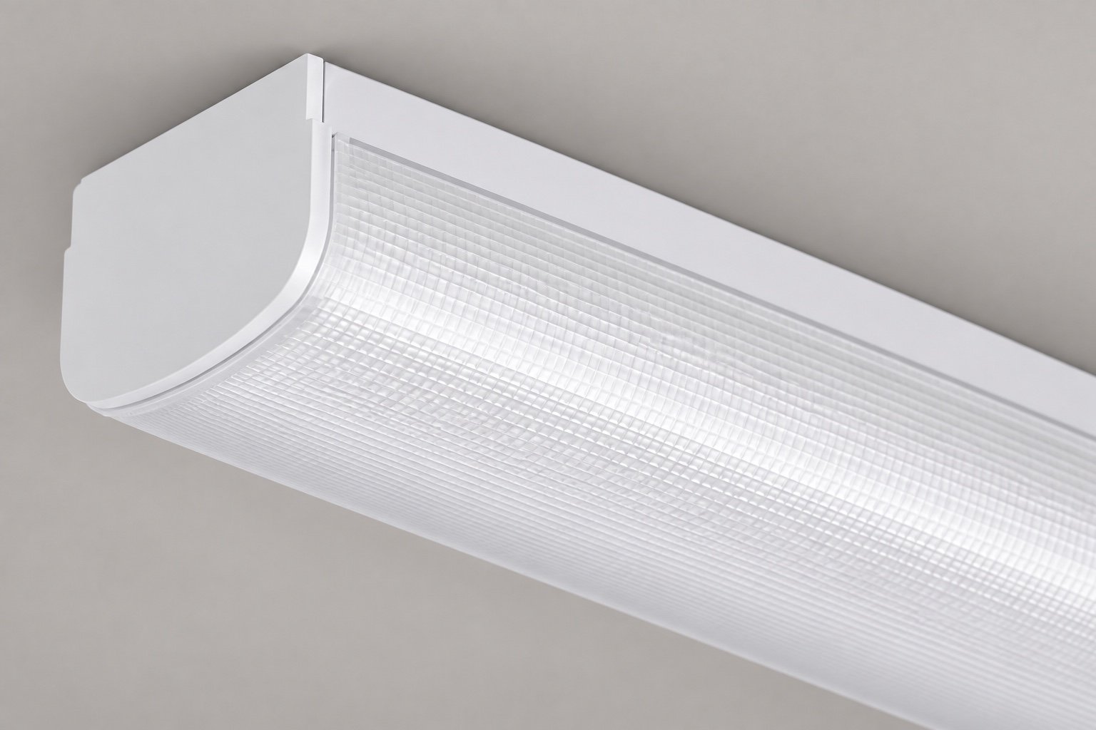
The optical stack includes the elements between the source and the emitted distribution: a lens, cover, reflector where used, and the surrounding aperture. A material’s transmission figure does not describe every light interaction in that assembly. The part’s surface, geometry, location and relationship to the LEDs matter to the candidate design.
A replacement must suit the source layout as well as the opening. Board position, lens alignment, cover retention and end-cap clearance should appear in the proposal. A part that fits the visible width may still require a different mounting plane or carrier. Manufacturer documentation such as LEDiL’s linear-lighting guidance is useful for understanding how linear optics are organized around particular source arrangements and distributions.
For a retained housing, compare the existing interfaces with the proposed ones before choosing between a component replacement and a local structural change. In an extrusion, the limiting feature might be the optical retaining interface. In a formed sheet-metal body, it might involve a folded edge, cover support or assembly access. These are drawing-review questions; exterior photographs do not establish the hidden interfaces.
The sample should also be assembled in the intended sequence. A cover that can be positioned loosely for an optical trial may not yet represent a production-ready retaining arrangement. Mechanical fit and optical behavior need to be resolved on the same proposed configuration.
Choose the distribution for the actual space
DLC category criteria and project lighting goals answer different questions. Qualification criteria apply to the product; an application comparison asks how its light serves desks, circulation routes, rack faces or an open industrial floor. A category-appropriate product still needs an optical brief for its intended use.
| Application | Question for the optical brief | Inputs needed |
|---|---|---|
| Office linear lighting | How should task and surrounding surfaces be lit while controlling luminous appearance? | Workplane, spacing, viewing directions and ceiling arrangement |
| Corridor | How should light reach the route and adjacent surfaces? | Width, mounting height, spacing and wall conditions |
| Rack aisle | Is the priority the floor, vertical rack faces, or both? | Rack geometry, aisle width, mounting height and target surfaces |
| Open industrial area | What coverage is needed between mounting positions? | Mounting grid, work areas, height and obstructions |
A broad distribution is a candidate for wider coverage. A narrower distribution concentrates the comparison on a more confined target, while its effect on spacing and adjacent surfaces still needs examination. An asymmetric option introduces directionality, making luminaire orientation part of the installation information. These are qualitative selection principles rather than prescriptions for one optic per room type.
Direct and indirect components add the question of how much light should reach the task directly and how much should interact with upper room surfaces. Ceiling geometry and reflectance assumptions then become part of the calculation. There is no universal direct/indirect ratio for every indoor linear application, and an attractive luminous appearance does not establish the room’s lighting result.
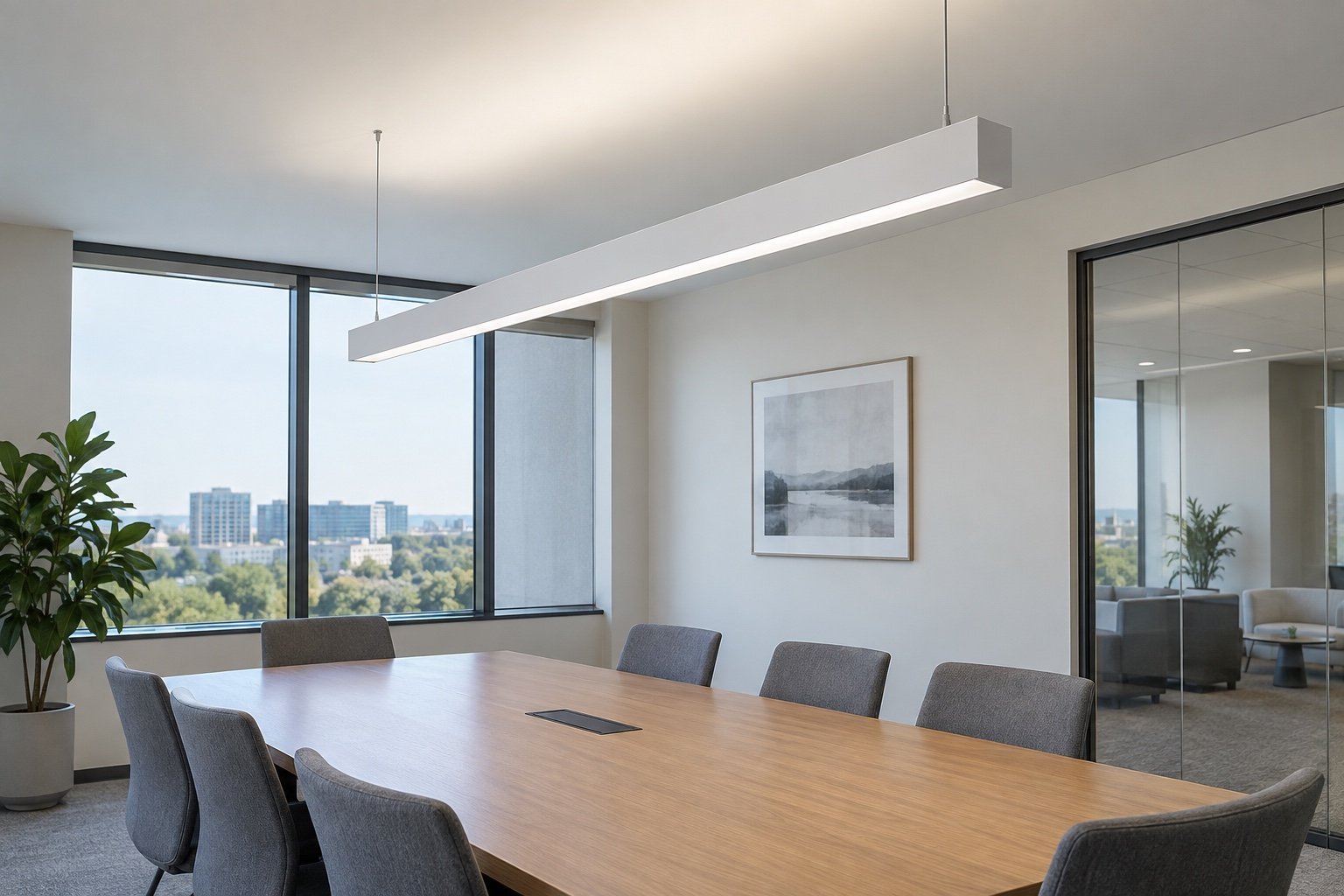
Compare efficacy, appearance and application trade-offs
Consider an illustrative redesign decision: an OEM compares its current diffusing cover with a less diffusing candidate. Even if the candidate returns a higher measured luminaire efficacy, the review still needs to address LED visibility, surface brightness and the changed distribution. Those questions should be written into the comparison before the sample is accepted, rather than discovered after an efficacy-led decision.
If the appearance is unacceptable, the next comparison might involve a different optical surface, a revised source-to-cover arrangement, or an alternative lens and cover combination. Each option has to fit the actual board and housing. The example identifies possible branches in the design review; it does not claim that any one change will deliver a stated improvement.
The preferred candidate should be judged against the customer’s priorities: required output, appropriate distribution, acceptable appearance and retained mechanical constraints. A higher lm/W value can coexist with light going away from the intended task. Conversely, a candidate that improves one viewing condition may introduce output or assembly trade-offs. The reason for selecting an option should name those consequences.
Glare requires a distinction between qualification and the customer’s application brief. Section 14.1 of the final V6.0 requirements removes Premium UGR requirements for Linear Ambient, High-Bay and Low-Bay PUDs while retaining them for Troffers. That change does not remove a customer’s visual-comfort target or make a material label a room-level glare result. The Felix diffuser and UGR article explains the limits of treating an optical surface as the complete answer.
Validate the complete configuration before extending the claim
A useful sample comparison records the model, drawing revision, LED board, driver, settings and optical part for every candidate. Output, input power and distribution should refer to that complete assembly. Where mounting, thermal conditions or control integration change, the project should identify the affected evidence with the laboratory and application owner.
For the application comparison, hold the layout and calculation assumptions steady while substituting the relevant measured IES files. Keep mounting height, spacing, target surfaces and reflectance assumptions visible in the report. An optical prediction can guide development, but it should remain distinguishable from complete-luminaire measurements. A generic beam sketch cannot replace either record.
The DLC product-update guidance connects testing and supporting documents to the extent of the change. A successful sample does not automatically establish coverage for every length, power or optical option. The final configuration matrix should identify which models the evidence represents and which variations need separate review.
Discuss a linear-lighting optical redesign with Felix using the current report and IES file if available, the target category and level, mounting height or intended layout, and a section showing the board and optical interfaces. Include the appearance and housing conditions that must remain. Felix’s optical and mechanical support can then focus on a set of candidate arrangements and the validation needed to compare them.